Selecting and implementing a power supply for a critical safety application requires a meticulous approach that goes beyond checking voltage and current ratings. The HIMA F7126 Power Supply Module is a specialized component whose correct specification, installation, and maintenance are integral to the validated state of the Safety Instrumented System (SIS). This guide provides engineers and procurement specialists with a detailed, practical framework for working with the F7126, from initial system design to long-term operational integrity.
Detailed Technical Specifications and Configuration Options
A precise understanding of the F7126's capabilities is essential for proper system design. While always consult the official HIMA data sheet for the specific revision, the module's typical specifications form the basis for integration.
-
Electrical Characteristics:
-
Input: Wide-range 85-264 V AC, 47-63 Hz. This universal input simplifies global deployment and provides inherent tolerance to line voltage fluctuations.
-
Output: Nominally 24V DC, with a specified current rating (e.g., 5A, 10A, 20A depending on the exact F7126 variant). The output is regulated and filtered to provide low ripple and noise, critical for digital logic circuits.
-
Efficiency: High switching-mode efficiency (>90%) to minimize heat dissipation within the control cabinet.
-
Protections: Standard protections include protection against overload, short-circuit, and overvoltage. These are "last resort" hardware protections for the supply itself.
-
-
Safety and Diagnostic Features:
-
Status Relays: The key diagnostic feature. The module provides electrically isolated relay contacts (e.g., one "DC OK" and one "Failure" contact). The "Failure" contact activates for any internal fault, loss of input AC, or output voltage deviation.
-
Redundancy Concept: The F7126 is designed for parallel operation using a dedicated Redundancy Module (e.g., HIMA part number for a redundancy coupler). This module ensures proper load sharing and isolation, allowing for hot-swap replacement of a faulty power supply without interrupting the 24V bus.
-
-
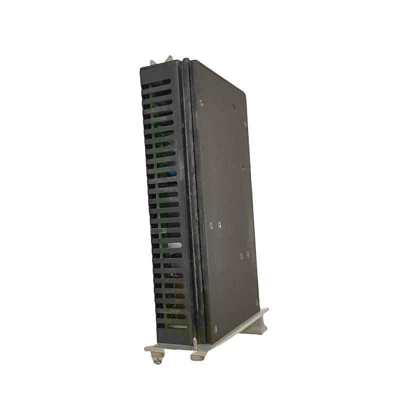
Mechanical and Environmental:
-
Designed for mounting on a standard 35mm top-hat DIN rail.
-
Operating temperature range typically -20°C to +60°C, with possible derating at the upper end.
-
Conformal coated printed circuit boards for protection against humidity and contamination.
-
Application Engineering: Integrating the F7126 into Your SIS
1. Sizing and Load Calculation:
The first step is a meticulous load calculation. Sum the current consumption of every module in the safety controller rack: CPU, all I/O modules (accounting for both their internal draw and the power they supply to field sensors), and any communication couplers. Apply a safety margin (often 25-30%). The total load must be less than the rated output of a single F7126. In a redundant configuration, the load should be less than the rating of one module, so the remaining module can carry the full load upon a failure.
2. Redundancy Scheme Design:
For high-availability applications (which is most safety systems), a redundant power supply configuration is standard. This involves:
-
Two identical HIMA F7126 modules.
-
One HIMA Redundancy Module.
-
The AC input for the two F7126 units should be fed from two independent, preferably diverse, power sources (e.g., different distribution boards or an Uninterruptible Power Supply (UPS) feeder and a normal feeder). This protects against a common cause failure in the AC supply.
-
The "Failure" relay contacts from each F7126 must be wired to separate, supervised digital inputs on the safety PLC. This provides discrete diagnostics for each power supply leg.
3. Wiring and Installation Best Practices:
-
Grounding: Follow strict grounding rules. The functional earth connection on the F7126 is critical for noise immunity and safety and must be connected to the cabinet's ground bar with a low-impedance connection.
-
Separation: Maintain separation between AC power wiring (to the F7126 input) and the sensitive DC control wiring (from the F7126 output). Use separate cable ducts or maintain a minimum distance.
-
Labeling: Clearly label all wiring, especially the diagnostic alarm contacts, in accordance with the loop diagrams and installation documents.
Procurement, Validation, and Lifecycle Management
-
Sourcing Authentic Components: For safety system parts, sourcing from HIMA-authorized distributors is paramount. Counterfeit or grey-market components may not have undergone the rigorous design and testing processes required for safety applications and can invalidate the system's SIL certification. Request certificates of conformity.
-
Proof Testing and Documentation: The diagnostic alarm contacts of the F7126 are part of the SIS's proof test procedure. The test, performed at the interval specified in the Safety Requirements Specification (SRS), involves simulating a failure (e.g., disconnecting one AC feed in a redundant setup) and verifying the correct alarm is generated in the safety controller and the control room. Results must be documented as part of the plant's safety lifecycle management.
-
Spare Parts Strategy: Given the criticality, holding a validated spare F7126 module on-site is a best practice. The hot-swap capability allows for replacement during normal operation, but the spare must be pre-configured (if applicable) and ready.
Conclusion: A Component in the Safety Lifecycle
Ultimately, the HIMA F7126 is more than a black box that converts AC to DC. It is a safety-critical component with defined failure modes, diagnostic coverage, and a direct role in the system's reliability calculations. Its specification, installation, and testing are not electrical tasks in isolation but integral steps in the broader functional safety management system. By applying the rigorous approach outlined in this guide, engineering and maintenance teams ensure that this fundamental pillar of their Safety Instrumented System performs its silent, vital duty with uncompromising reliability.